A new cache is under construction. And what a kind of a cache! It will be (up to now)
- the most complicated one (in mechanics)
- the most expensive one (in Euros and Dollars as well) and
- the sketch will be the longest one ever (more than 1300 lines of code actually and still increasing)…
But, from the beginning: Some weeks ago I thought about using a laser with a cache. No real plan on it, but I just bought 3 laser break outs (http://www.amazon.com/FORWORD-KY-008-Transmitter-Sensor-Arduino/dp/B015XJXW0M/ref=sr_1_3?ie=UTF8&qid=1456211650&sr=8-3&keywords=Laser+Arduino). They aren’t expensive – you can buy 5 for a price of 9$.
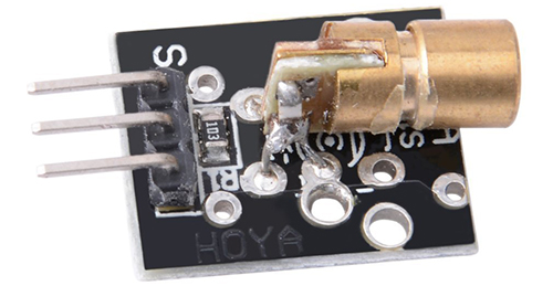
When the laser break outs arrived, I quickly tested one of them. Impressive: They are quite bright (brighter than an usual laser pointer) and the laser beam is focused very good. During dawn I sent the beam through the window of my office at home to the wall of another house roughly 300 meters (1000 feet) away and I was able, to see the laser point quite well.
Meanwhile a lot is done and the setup of the cache ready:
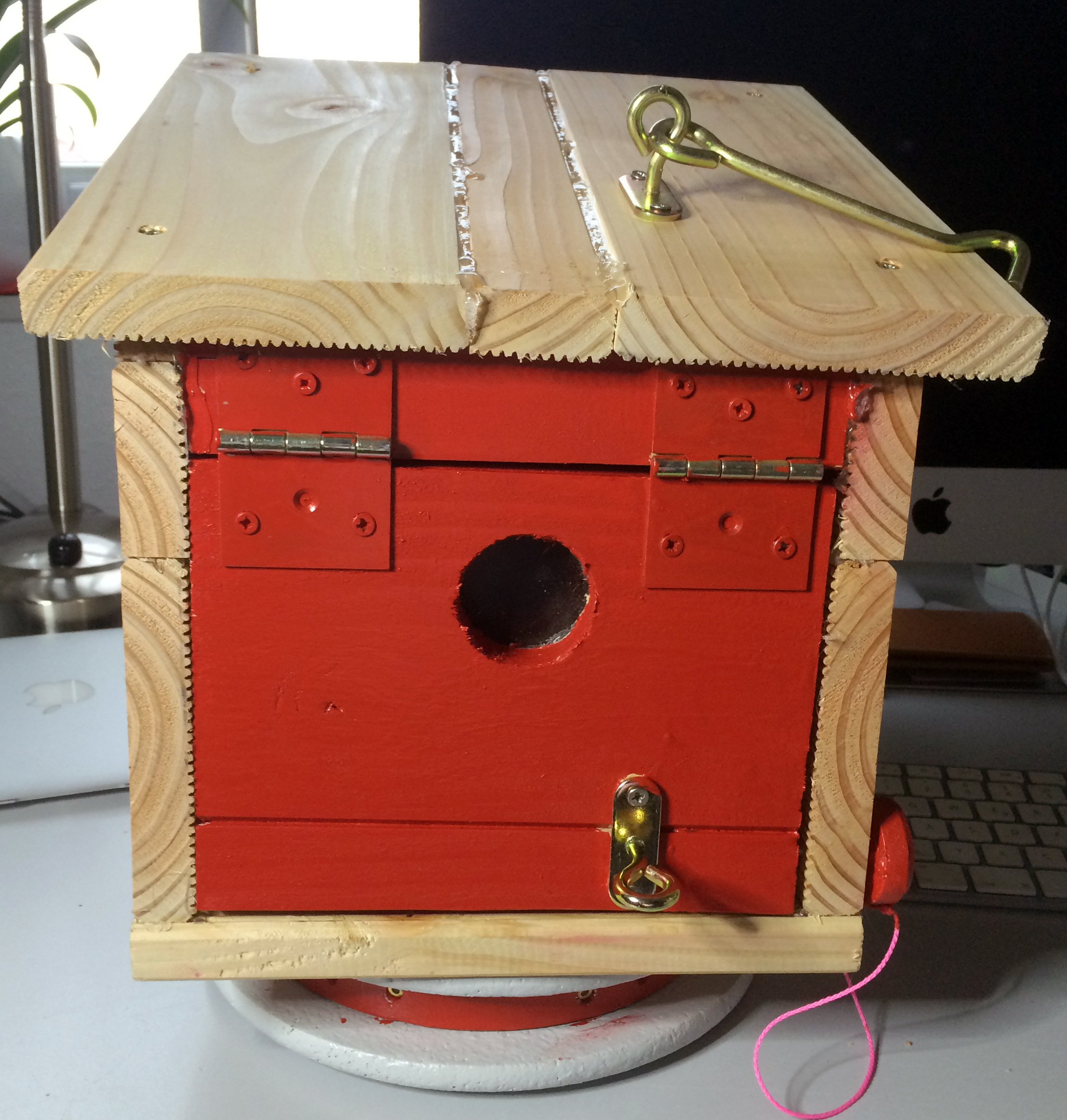
It will be a night cache – or at least a “dawn cache”. When the cacher is arriving at the cache, he’ll see a “typical housing”. Typical housing means, that Tim will put it into a kind of a bird house while I’m building a case of Douglas fir.
On the bottom there will be a Plexiglas dome with the laser inside. The laser is mounted to a construction of 2 stepper motors and can be turned horizontally and vertically.

Building that, we have to ensure, the laser would never go into the eyes of the cacher directly. So when beaming horizontally, it shouldn’t be higher than 5 feet. But there will be warnings because the cacher might be accompanied by a child or a dog…
After the cacher has solved a quiz about lasers, the laser will beam to the final hide of the cache.
The final hide shouldn’t move. My idea is, to dig a short pipe into the ground containing the final cache container (e.g. a petling?). This final hide will be quite well camouflaged (e.g. by a lager stone) to avoid someone will locate it by chance.
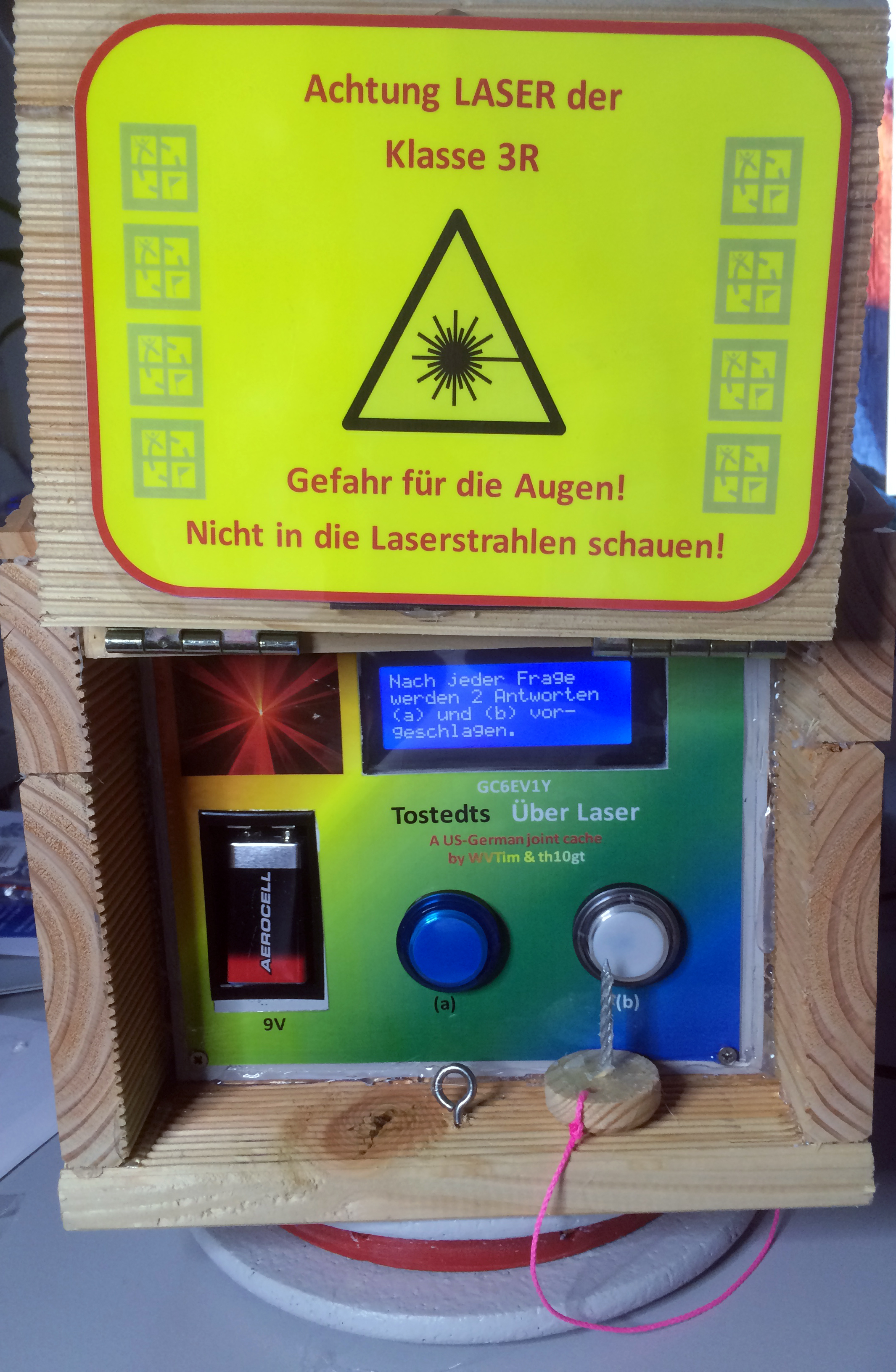
I’ve talked about a quiz. When putting his battery into the holder and powering on the cache, there will be 10 questions coming up regarding lasers. Every time 2 possible answers are proposed and the cacher has to choose the correct one by pressing one of two buttons. At this moment he needs to answer at least 7 of 10 questions correctly to force the laser to beam to the final hide of the cache. If less than 7 are correct, the quiz will start over again. So a kind of preparation at home would be fine.
Battery? The battery of the cacher will power on the Arduino. But for the motors we’ll need much more power. So we need to integrate a separate high power battery inside the cache. I did so with my Fire & Water cache and up to now there wasn’t any charging of that separate battery needed.
Some “highlights” of the construction:
The Plexiglas dome:
I was surprised, that such domes are quite expensive. The first one I’ve ordered had a diameter of 10 cm (4 inches). When it arrived, I was surprised again about how tiny it was. The laser construction would never fit into it. I swore to myself an oath never to order something by thinking, it should be ok but by measuring in advance. I looked for a bigger dome not being much too expensive and ordered one with a diameter of 23cm (9 inch). I didn’t wrote, I followed my oath and was again very surprised, how large that dome was. I expected something just a little bit larger than twice of the first one. But with a ball (and a dome is half of a ball) the size is going up as the square of the diameter. So this dome is more than 5 times large as the first one.
Usage of EEPROM memory
Tim and me discussed a lot, how to finally implement the coordinates of the final hide into the sketch (the program). My idea was quite silly, because we would need to drive three times to test something at the final destination and then driving back home to update the sketch. Another drawback would be, that each time the housing must be precisely adjusted as it was before.
When I talked with a colleague of mine during lunch, he dad a quite better idea:
- During power on of the sketch you need to press both buttons to bring the cache into a kind of a setup mode.
- By pressing the one key the laser will move one step horizontally, pressing the other one vertically.
- When the laser is pointing to the final destination press both buttons and the position will be stored.
That’s for sure a much better idea. But soon a question came up: “How to store values with an Arduino?” I never did it before. After some googling I found, that the Arduino is offering some addresses in its EEPROM for such kind of usage. There’re at least 255 addresses available (with an Uno, with a Mega much more) which are able to store 1 byte (an integer value between 0 and 254).
But how to store something like “-182.71” degrees? I solved that very easily by using 3 memory addresses of the Arduino by splitting such a value into 3 pieces:
- First one: The integer part of the figure = “182”
- Second one: The decimal part of the figure multiplied by 100 = “71”
- Third one: The sign (0 = positive, 1 = negative) = “1” meaning negative
Conversion back is quite easy: First value + (second value / 100). If third value is “1” the value is negative.
By working on the sketch to implement that, I had the idea to include a kind of a visitor counter also. But how to manage the 255th visit? I solved that, by splitting the value into two pieces. Here’s an example how to store “578” into the EEPROM:
- First value: divide 578 by 254 and keep the result as integer = 2
- Second step: multiply 254 with the result (2) above = 508
- Third step gives the second value: 578 – 508 = 70
- The “2” and the “70” will be stored in EEPROM
Conversion back is also quite easy: (First value * 254) + second value.
Because all that was working so fine, I expanded the EEPROM usage also to store the values of the brightness of the LCD display and the LEDs of the buttons as well.
I integrated a setup part inside the cache, which can be selected, when pressing both buttons at the beginning of the sketch. Up to now 5 setups can be done:
- Calibrate the laser to the final destination of the cache
- Set the amount of visitors to “0”
- Let the laser beam to the final destination (more a check than a setup)
- Adjust and store the low and high brightness of the LEDs
- Adjust and store the brightness of the LCD display
Calibration of the laser beam
The idea of calibrating the laser beam came from my colleague, but I modified it. My aim was, to work with roughly 1/20 degrees precison at the end, but not offering the need to press the buttons thousand times. So the calibration will work in 5 steps like that (I’ll explain only the horizontal calibration. The vertical one is quite similar):
- Step angle is set to 25°
- Laser will beam to an angle of -180°
- By pressing the key, the laser will move by 25°. After the first press of the button it will beam to -155°
- You’ll have to press the button up you’ll be nearest to the final. Let’s assume you did it 10 times. So the angle is now -180 + (10*25) = 70°
- The laser will go back 3 times the Angle step. So it will flash now to 70 – (3*25) = -5°
- The second step of the calibration will start and the step angle is now reduced to 5°
- You’re pressing the key e.g. 12 times and the new angle is -5 + (12 * 5) = 55
- The laser is going 3 * 5° back to 40°
- The third step will start with step angle of 1°
- After you pressed the button e.g. 13 times the new angle is 40 + (13*1) = 53.
- The laser is going back 3*1 ° to 50° and the step angle is set to 0.2°
- After pressing the key e.g. 11 times you have finished the fourth step and the angle is 50 + 11 * 0.2 = 52.2°
- Again the laser goes 3 times 0.2° back to 51.6° and the latest step angle is set to 0.04°.
- After pressing the button e.g. 12 times the angle is finally defined as 52.08°
The moving back of the laser 3 times the current step angle should avoid problems, when pressing both keys too late to set the current position. But maybe instead of three times two times may be sufficient. This would reduce the need pressings of the button by 5 at each of the 5 steps (so by 25!). Testing will prove…
24.2.2016
For long I was waiting for the couplings of the motor. They’re looking like this:

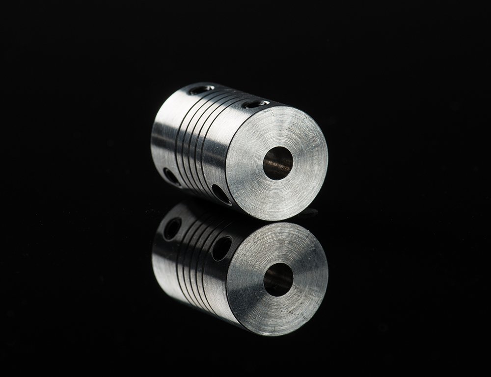
The original one from Adafruit is offered by Amazon, but for a price of roughly 10$ each. I ordered 10 via eBay and the price for 10 was roughly 40$. Unfortunately I’ve chosen “free delivery” and so the slowest snail of German snail mail has been tasked as logistic company. When they still not arrived on Sunday, I ordered again 4 from another company. They looked exactly the same, but it was said, they would be from Adafruit. The price was 6$ each (still quite less than Amazon).
Yesterday both orders arrived. The couplings are locking exactly the same. But, when holding them in your hand, the weight of the Adafruit ones is quite less (I think 20%). So I used them for the hardware setup of the motor holding.
Here’s a short video on how it’s working:
As ever: By clicking the YouTube button, you can watch it in 1080p…
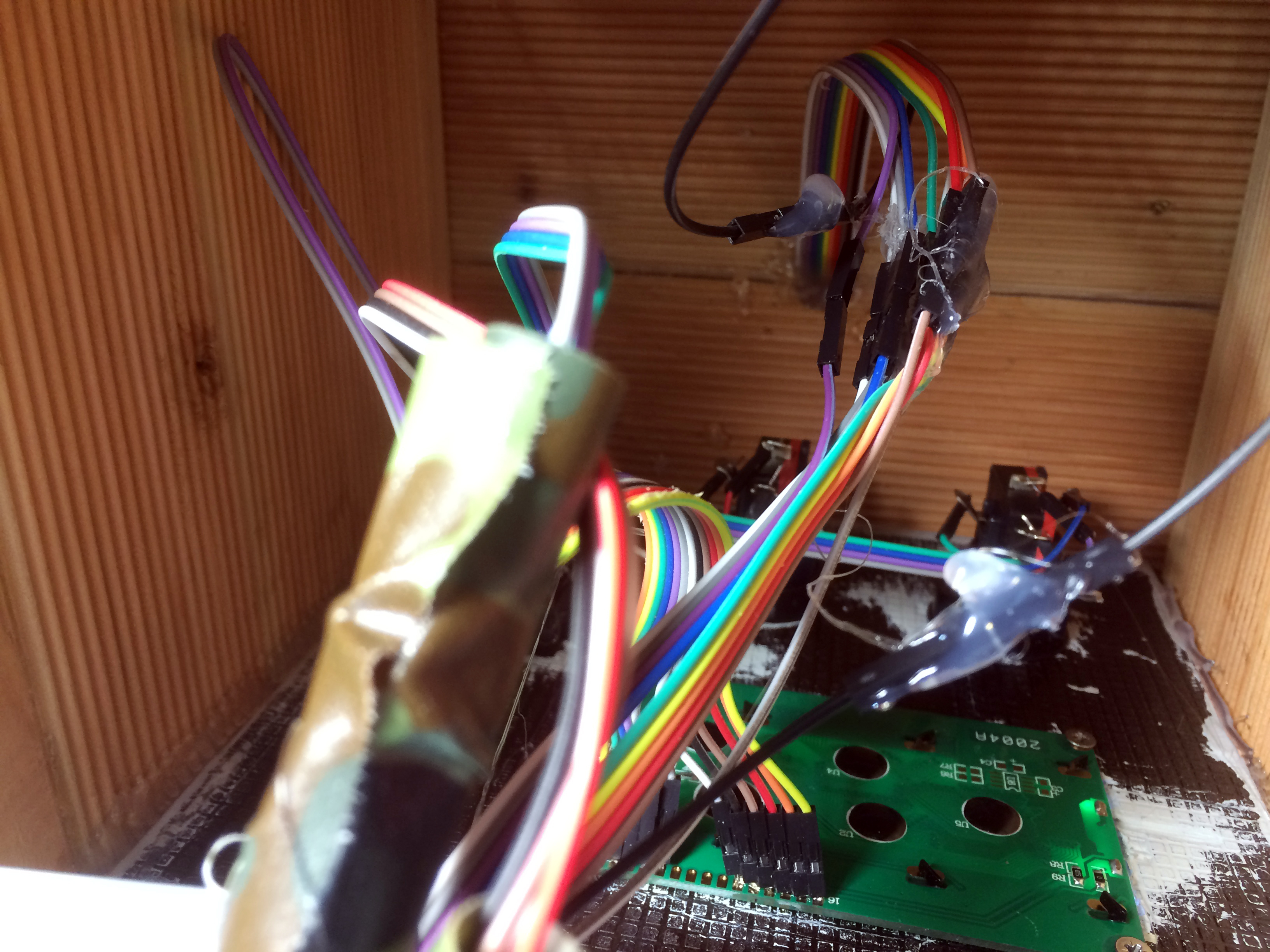
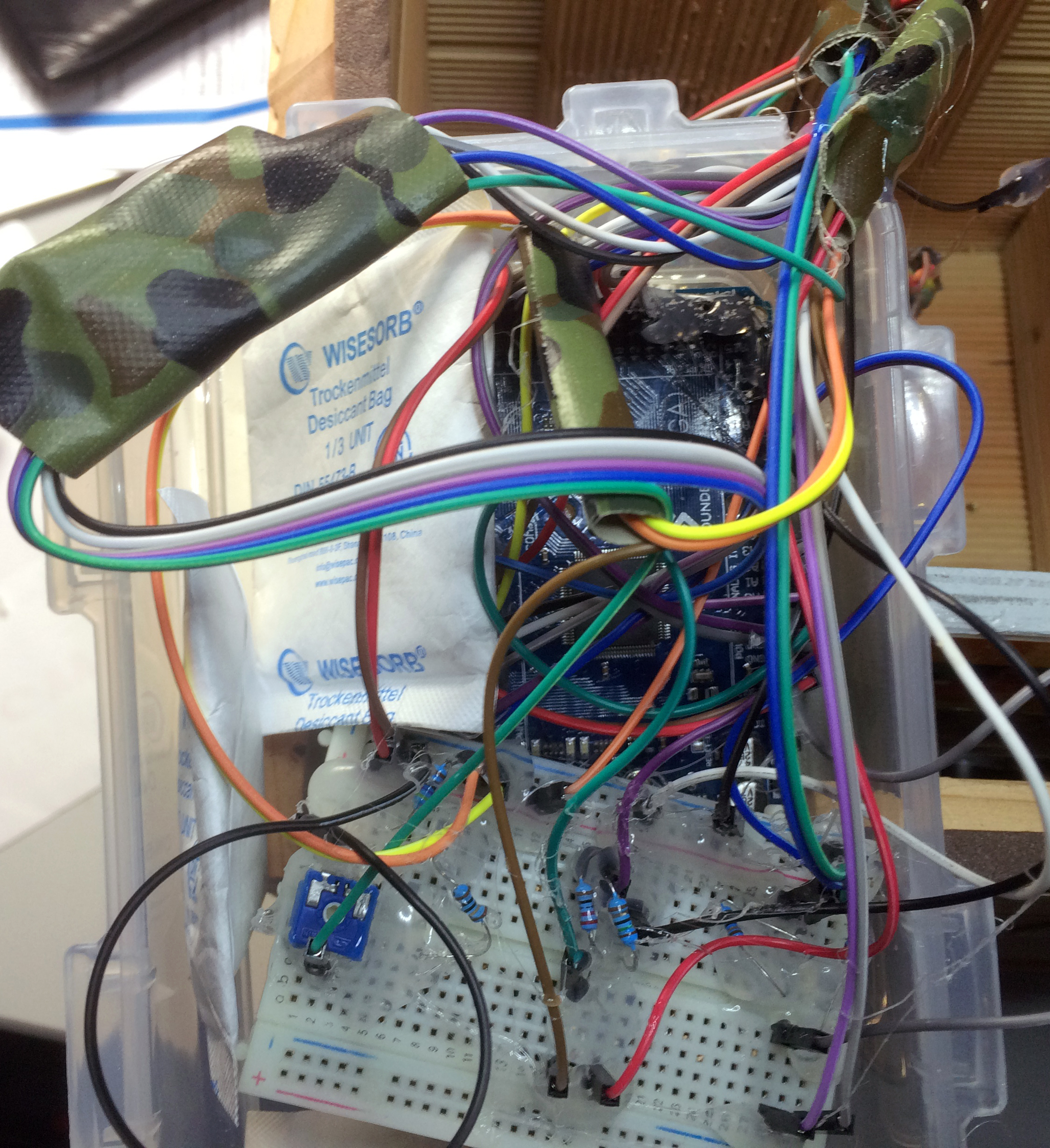
Step by step I’m now testing the roughly 1,300 lines of code I’ve written during the last days. Here’re some better pictures of the hardware setup and a video about the initial „laser show“. This will be shown after the cacher has powered on the cache and prior the questions are coming...
As ever: By clicking the YouTube button, you can watch it in 1080p…
25.2.2016: Both – success & drawback
Yesterday I had some time to work on the prototype. The “laser show”, which will be shown at the beginning, is working quite well. The video above is showing an example.
Next step was to work on the calibration of the laser beam to the final location of the cache. As ever, the software is quite buggy at the beginning. But in this case it’s annoying. Every time you need to stop, both motors are’ntt at their initial position So you need to update the sketch and try to bring both motors back to their initial position. After that you can start with bug fixing. But if you’ve forgotten to skip the lines, you just used to bring the motors back to their initial position, you can just start over with that again. Quite time consuming and annoying…
Another drawback – at least for testing – is, that the horizontal motor can’t perform a full turn. The stand isn’t large enough to avoid the motor hitting the stand. I’ll built a new one during weekend.
I talked with my colleague again (the one who had the idea with the calibration step) and he brought up again an advice, he told me already some days ago: “You need to discover at start a precise initial positon automatically!”
What does he mean? At this moment my sketch relays at the beginning, that both motors are in their initial position. But, at least when testing and the sketch is still buggy, most of the times they aren’t. So I need to add something, that the motor is adjusting itself and automatically to the initial position.
How to do that?
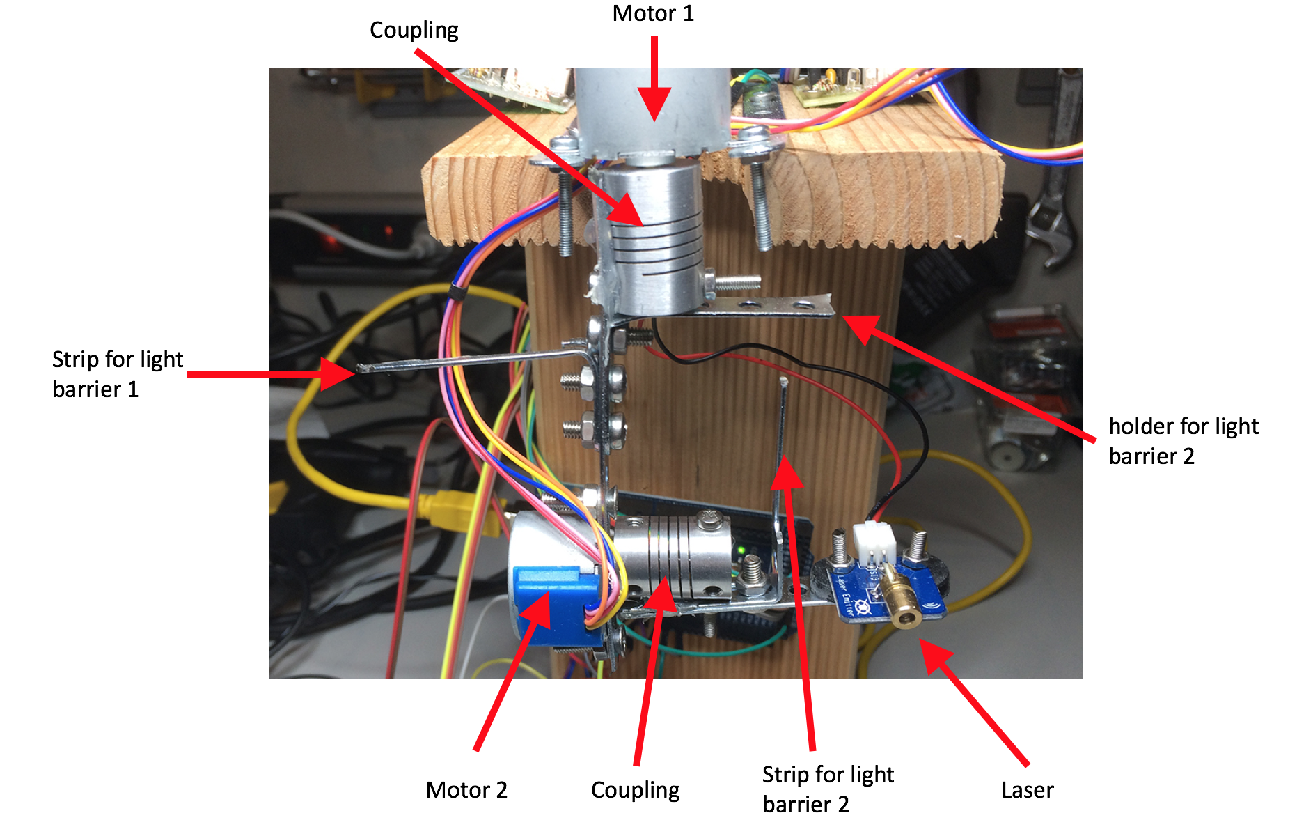
My colleague proposed, to do that with a light barrier. More precise with two light barriers for the 2 motors. Every time prior the motors will start to do something, they will find their initial position. Here’s an update of the mechanical setup.

This is the way how it will work (explained by the horizontal motor only): At the beginning the motor will stepwise turn left and right in continuous larger angles up to the strip will reach the light barrier. The motor will stop and this position will be set as the initial position.
It sounds not so difficult, but I’m wondering, whether I’ll be able to build it (and not only to write the sketch). The light barrier for the first motor must be fixed to the housing itself. This should be feasible. But the one for the second motor must die fixed to the first motor. This will be (at least for me) a real challenge…
To make the initial position of the motors as precise as possible, I won’t just stop the motor, when the light barrier wents below a certain threshold. I’ll do it more precise by a fine adjustment, when reaching the light barrier. I’ll explain now (for sure, it’s more complicated, because I need to take into account, from which side the the light barrier was reached. I’ll skip that for my explanation.):
Here’s a more precise explanation how it should work:

26.2.2016: The 2 left hands did it!!!!
I’m still waiting for the light barriers which will arrive tomorrow. But I’m quite surprised that I was able to built up a new prototype holder and the mechanics of the motors within 2 hours. What’s going on with me? Just have a look to 2 pictures of the new set up:
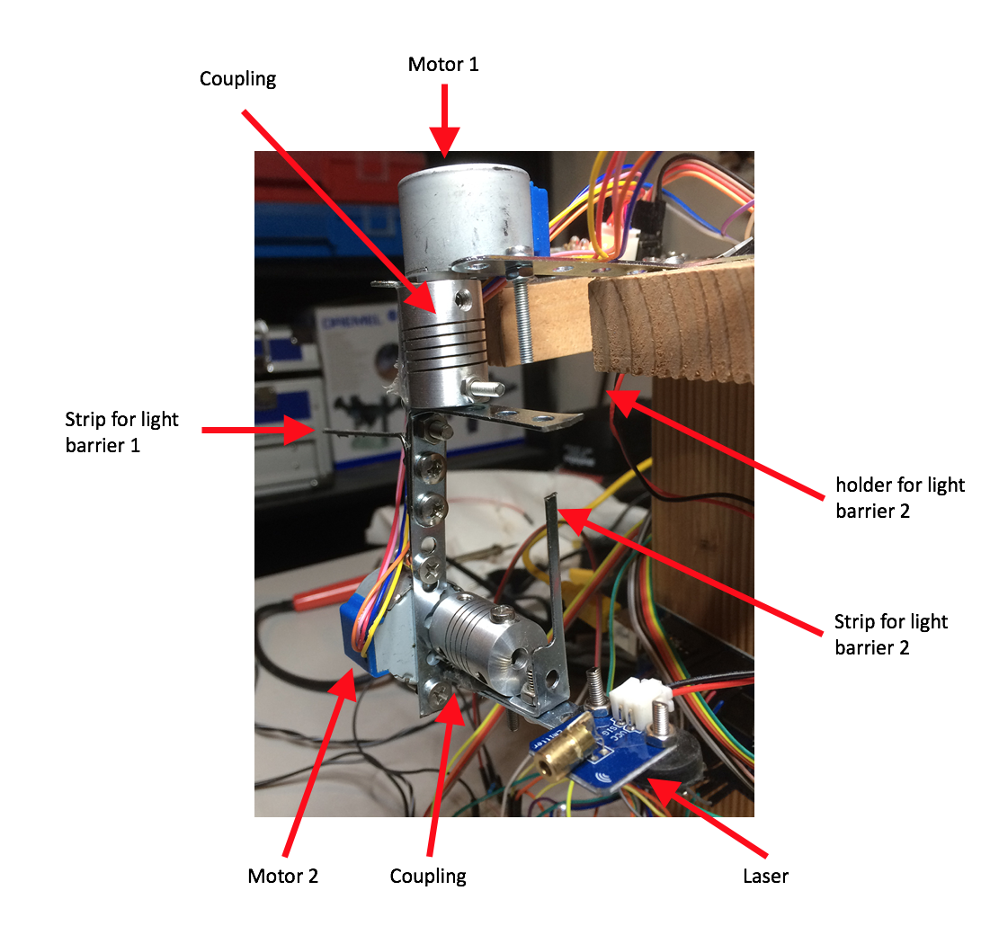
Tomorrow (Saturday) I’ll be very busy on other topics, but I hope to finish the complete setup during the weekend...
27.2.2016: Movie for the seminar and light barrier test
Today I was quite busy on other topics but I finally finished the video for your seminar. I’ll show it here quite soon… Also I worked on the light barrier. Yes, it’s working. But it took some time of gooling to investigate the connectors. The picture I found some days ago in the internet was unfortunately not matching with the ones; I’ve ordered.
But I just decided not to built the electronics by myself, because even when putting them onto a tiny breadboard, they aren’t handy. So I just ordered this ones already mounted onto a small breakout:
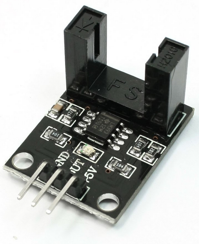
Now I’m owning 20 single light barriers in addition. The time will come, when I’ll need them…
4.3.2016: Self adjustment working!
I did it!!! Here’s the proof (as ever - hitting the YouTube button will give you the chance to watch in 1080p!):
As ever: By clicking the YouTube button, you can watch it in 1080p…
13.3.2016: Prototype working...
And here’s now a video of the final version of the prototype:
As ever: By clicking the YouTube button, you can watch it in 1080p…
18.3.2016: Starting over from scratch….
What I’ve wrote above, was correct. But I played a lot with the prototype and I discovered, that I’m quite sure the mechanic part would lead of a kind of „maintenance every day“.
So I decided to go a complete different way.
You think, I’m disappointed about? Yes, you’re right, but only a little bit. Even with a lot of grey hairs on my head, I still love to learn and to come up with „great logical“ ideas. And that was the case, when working on that prototype. Especially the „self adjustment“ of the two motors was a challenge for me and I’m still proud about the idea how to do it, to programm it and finally to discover, it was working so great.
But again: That was a very challenging approach, but not useable for a real cache. Maybe someone other, reading this blog, will keep this idea and will bring it to real life in future. But not me...
Instead of moving one laser around, I’ll work with 10 fixed ones. My idea is to make a resin block with the lasers in them.
A first test proofed that the lasers are working fine inside the resin block, but if the lasers are really inside the block, the optic doesn’t work. Instead of a sharp laser beam coming out of the block it’s more sending something like a torch. I didn’t polished the block, but I drilled holes into it. As deep as possible not damaging the lasers. There can be only a coating of the thikness of a hair above them, but the result didn’t changed. Yes really it was exactly worse as with a little bit less than a centimeter above them.
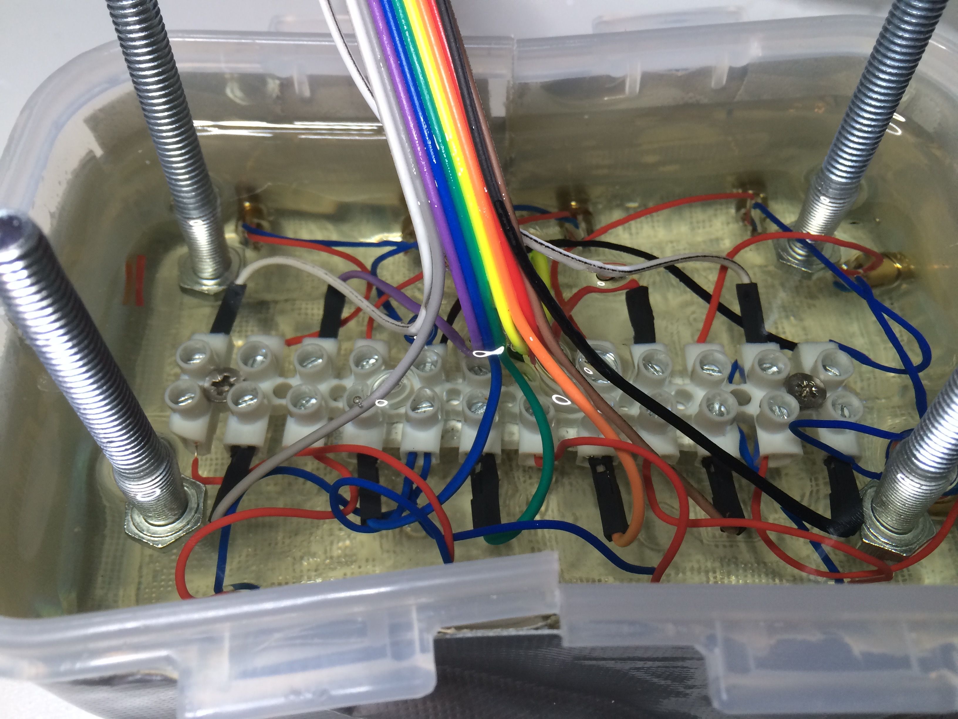
Today I started with a new approach: The form is a Lock&Lock and I put 1ß holes into it. The lasers are sticked into the holes. To be able to remove the form from the resin block, I cutted the form into 4 pieces and taped it together. The picture below is showing the form with the lasers and the first layer of the resin.
When the first layer will be hard (I hope tomorrow) I’ll bring together all blue cables (Ground) and each of the red ones into a lister connector, which will be completely covered by the second layer of the resin. From this lister connector 11 cables will go to the Arduino.
I’m also thinking about to bring 4 screws into the second (or third???) layer with their threads up to easily mount the final block to the housing. At this moment I’m not sure about…
19.3.2016: 1st Layer is fine
The first layer was hard this morning and I wired all the cables into a lister terminal - the smallest one, I was able to buy. All the blue cables (Ground / negative) should go into one connector. Because the cables are so short, they’re going to two, which are connected and will go to GND of the Arduino. All red cables are going into separate connectors and will go to the different pins of the Arduino. I tested all lasers in my office and they’re all working.
Back into my hobby room in the cellar I put a second layer of the resin on top.
Also I put the screws into the resin to mount the laser block easily to the housing.
The yellow cable has no meaning. I used it only to fix the white cable on the left to the others.
As you can see, breaking the form to four pieces to be able to remove it later, made the form a little bit ugly. I’ll have a lot to do for the final finish, but if it’s a little bit bent, this doesn’t matter. Main topic is, it will work…
20.3.2016: 2nd Layer caused a disaster...
Unfortunately the tape I used to fix the four parts of the form together wasn’t resin resistant. So some resin poored through it. This wouldn’t have been a big problem, but unfortunatelöy the resin went into most of the optics of the lasers. So they were still flashing, but not with a bundled beam. When trying to get the resin out of the optics, I’ve destroyed one laser.
As ever: By clicking the YouTube button, you can watch it in 1080p…
But one topic was interesting: The Arduino was able to power on all ten lasers without any problems with the power. This will give the chance for a great laser show at the beginning.
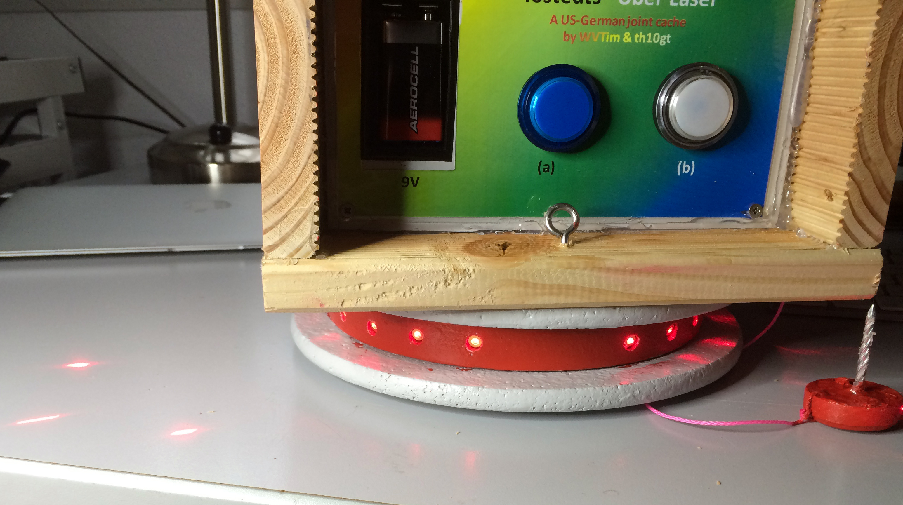
I’ll have now to go a third way. I’ll mount the lasers into a wooden ring like this:
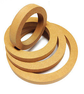
The rings are 0.9 inches high. So there should be enough space to mount them flashing not totrally horizontally but a little bit to the ground. Maybe I’ll put resin into the ring, when everything is mounted. Maybe not. I’ll think about during the next week…
I just ordered 20 new lasers and 4 rings…
26.3.2016: 3rd approach...
I received the wooden rings and discovered, that they’re made of something equal to wood, but not wood. They’re made from MDF (medium density fiberboard). Their „normal“ usage is, to mount loudspekers to them. Ok, with me it’s a little bit different…
Very carefully I drilled the holes for the lasers in and then I painted the ring the first time red. I think, I’ll need some more layers of paint…
I’ll mount the ring onto trivets made of cork, which I’ll paint too (maybe not the inside). I just ordered them:

The outside of the ring and the trivets have a diameter of 19 cm (roughly 7.5 inch), so the ring for the lasers will be closed at the bottom and the top as well by the trivets.
28.3.2016: … working!!!
So glad that I didn’t throw the towel. Here’s a first look on gthe prototype. For sure, there’s a lot of fine tuning needed (as ever: hit the YT button to watch in 1080p): Video just replaced by the latest one…
As ever: By clicking the YouTube button, you can watch it in 1080p…
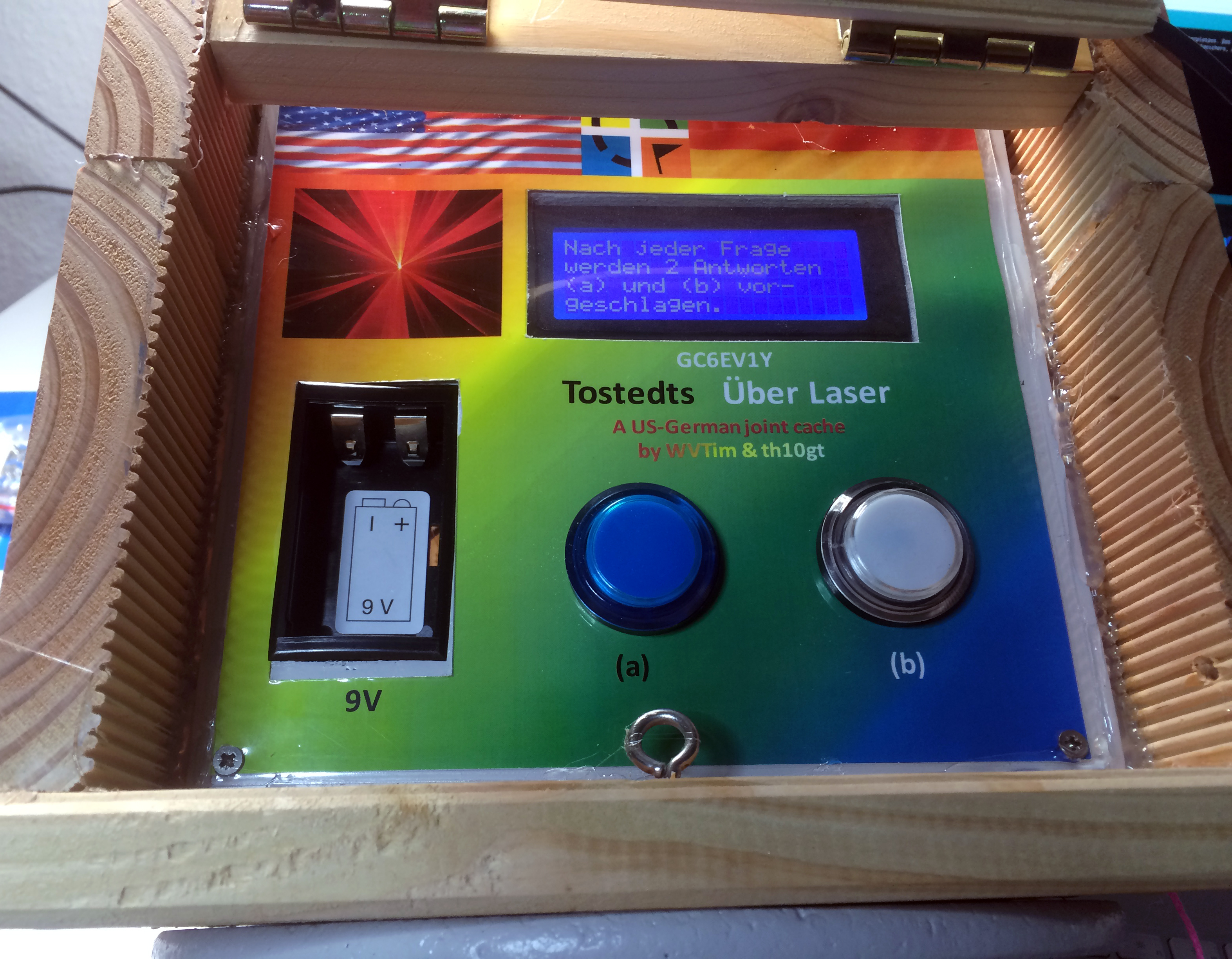
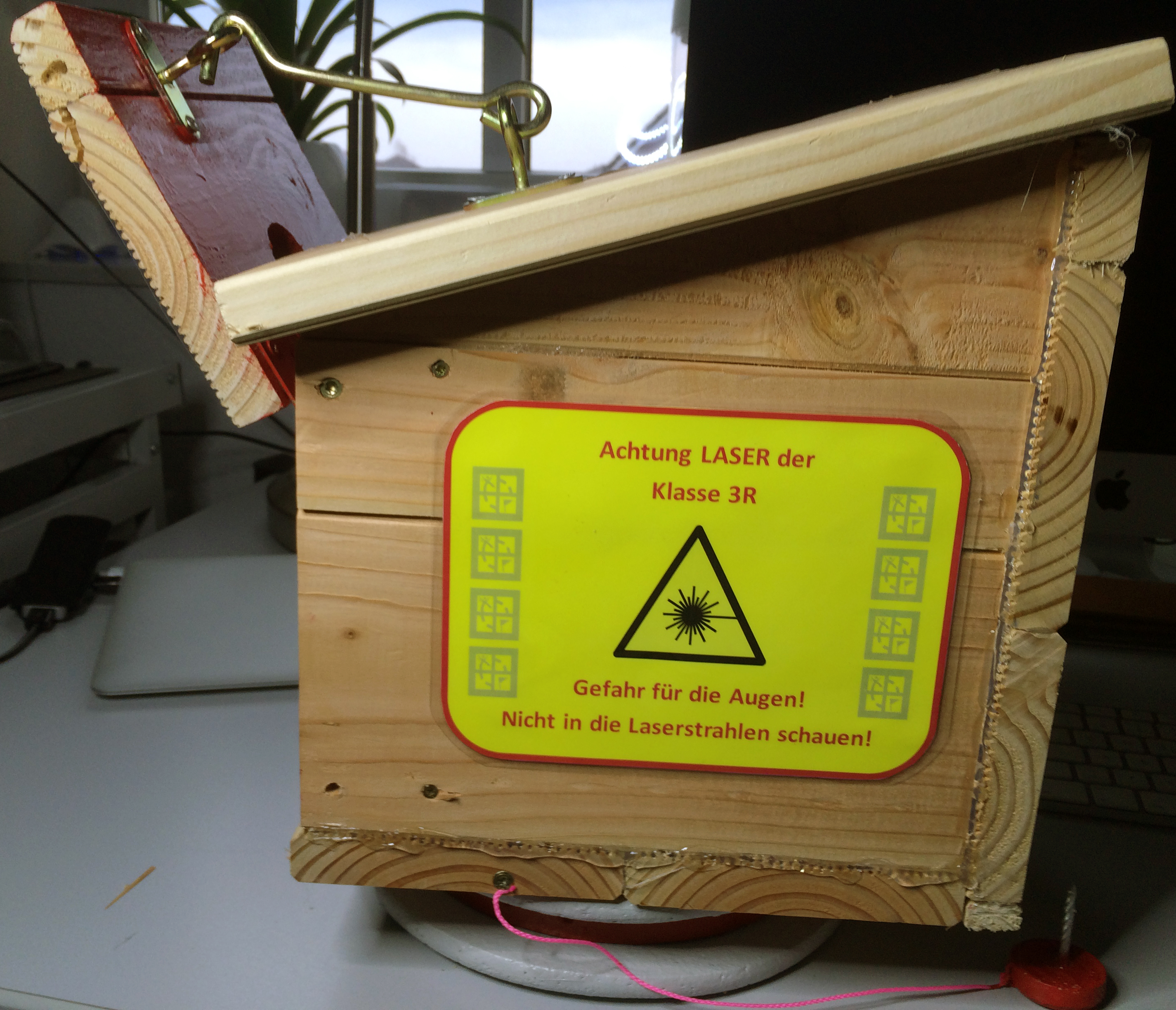
3.4.2016: … The housing is nearly finished!!!
I worked a lot on the housing during this weekend. It’s nearly ready. Have a look to the inside front panel:
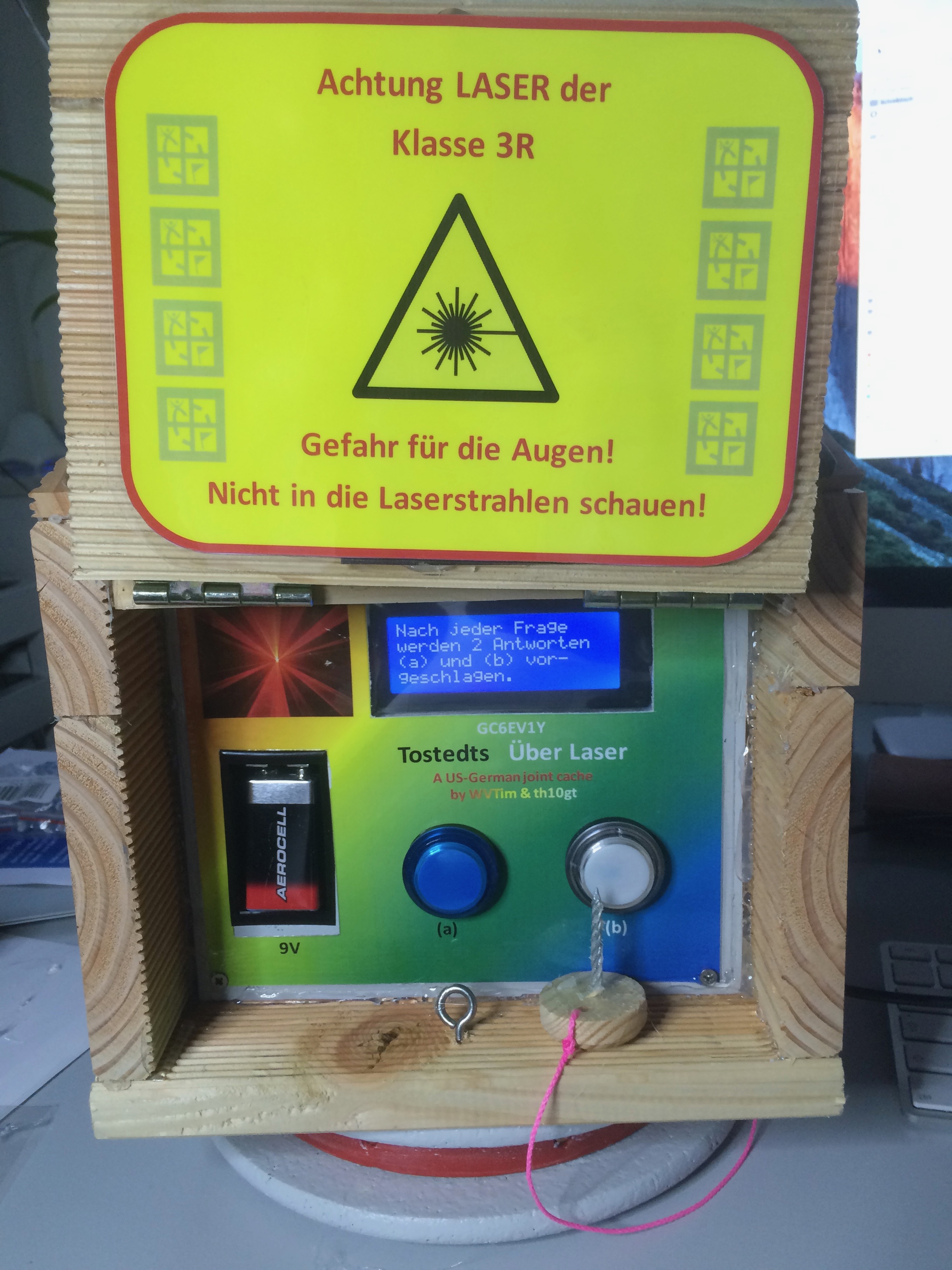
I’ve used the first time the new laminating device, a birthday gift from Tina. I’ve cutted out from the paper the rectangle for the LCD, but laminated all. So the LCD is covered by the laminate foil. Except below the battery holder it’s quite perfect, or?
I fear, I have nearly no time this week. So let’s see, if I’ll get it done next weekend...
6.4.2016: … DONE!!!
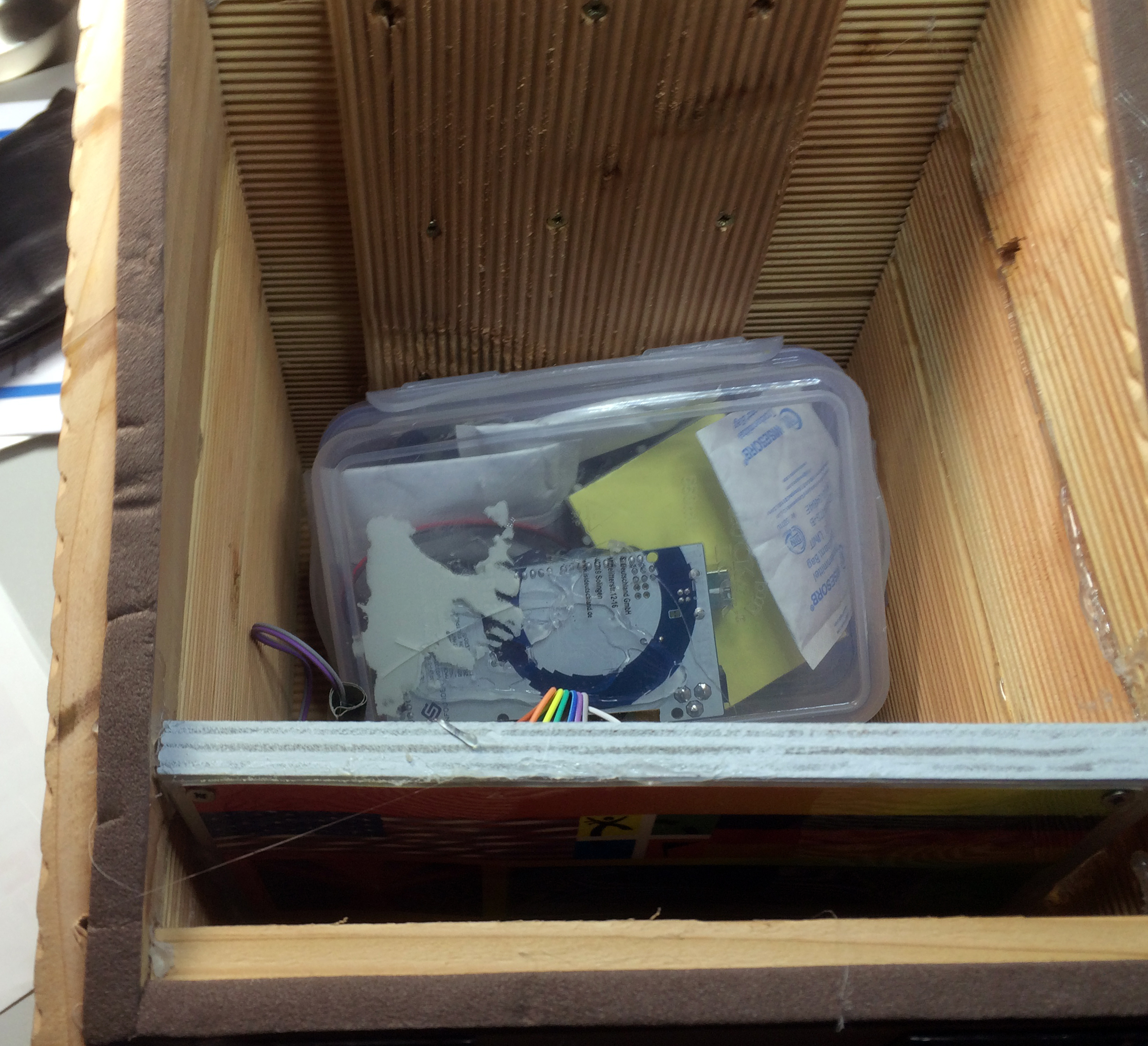
Have a look to the pictures below (click on them to see them in full size)… It’s done. Now I need to find a place. I fear, this will become a quite difficult task...


17.4.2016: …Looking for a place to hide
I just contacted two owners of hotels nearby asking them to place the cache on their property. Let’s see, what will happen…
You can pick the full sketch here…
Stay tuned!
Blog will be continued…